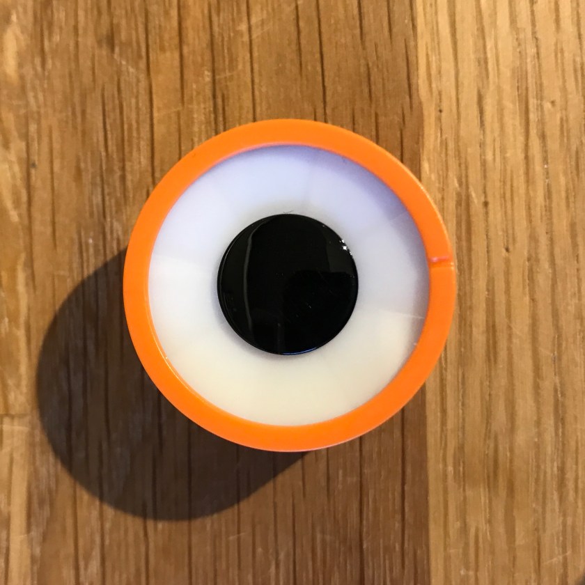
We continue taking apart the various Jimu Robot components. After the Controller and the Servo this time we will look at the LED Light.
From all Jimu components I have to confess that this one is the one that I really like the most. It is provided with a daisy-chained interface that makes it very easy to position it anywhere in the robot and, like all other daisy-chained devices you can stack a few of them in your configuration, as long as you set them up with different IDs. You can have a maximum of 8 of these LED Lights in a single bus (and the Jimu controller has only one logical bus – although uses 5 connectors, all are pin-to-pin connected). This limitation is driven by the communication protocol and the firmware in the LED Light, but sincerely I don’t see this as a worrying limitation.
The LED Light looks really nice and makes a very good addition to a robot. Wait until we put some power through this baby and you’ll see what I mean!
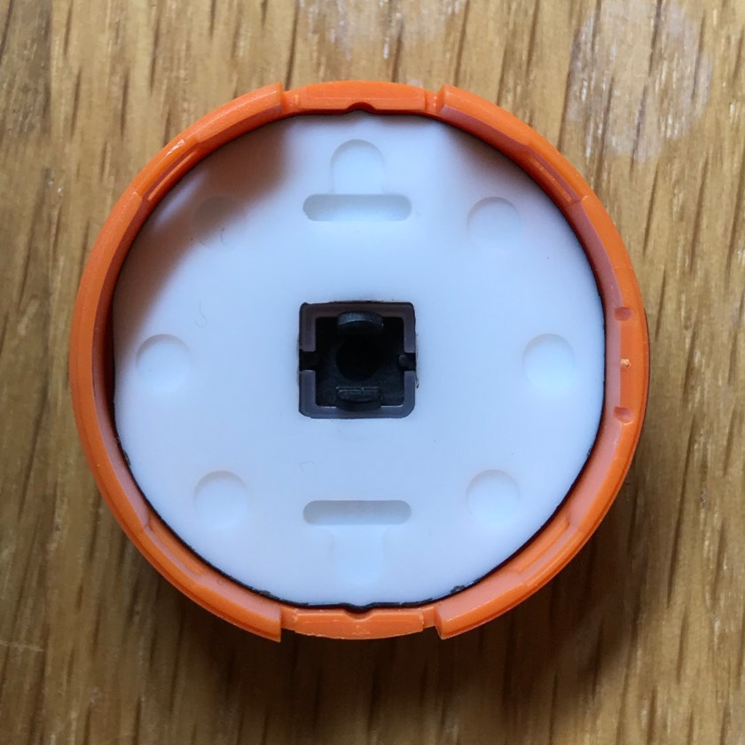
The back has plenty of connector holes that would make it very easy to fix this on almost any configuration available:

Now we’ve going to get in and see what’s in there. There are no screws, just some clamps on the side. Once opened the board looks like this:
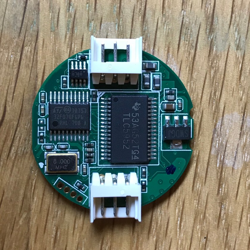
As expected the board includes an STM32F070 microprocessor (the same as in the controller board albeit in a 20 pin TSSOP package and with lower memory and Flash).
Above the processor there is the switch circuit that provides the semi-duplex TTL needed for the communication on the bus.
In the middle of the board there is a TLC5952 a circuit that provides programmable output for 24 channels or (as we have in out case) 3 groups of 8 channels (to drive 8 RGB LEDs). The chip allows also 128 levels of brightness for each of the groups. A real beauty.
On the right side there is an LDO that provides the power for the electronics and the LEDS.
Speaking of LEDs, they are located on the backside of the board in an octagon shape:
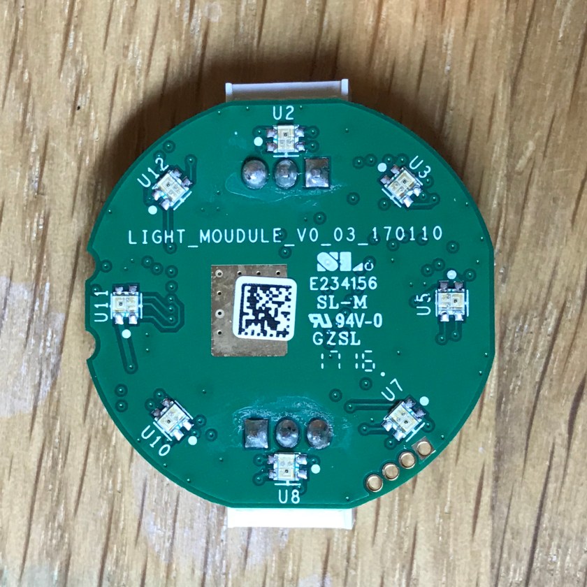
This arrangement is used by the semitransparent screen that is fixed on the LED light from cover, providing a diffusion of the lights within the segment of the circle they are located and isolation from the light coming from the neighbouring segments:
The microcontroller on the board provides the communication support with the controller and “speaks” the Jimu protocol. When various commands are received it translates that to lower level instructions for the TLC5952 circuit that ultimately will result in a pattern of lights being shown on the device.
What is really nice about this device is that is represents perfectly the idea of having “smart” devices connected over a daisy-chained bus that need only limited amount of information to perform quite complex activities that are coded in the firmware in the microprocessor.
For instance this LED light, apart from the (boring) commands that allow you to set the colour and the intensity for the 8 LEDs, there are a number of predefined “Shows” that can be played: there are 4 “show lights”, one of them for example being “Color Stacking”:
(A note here: the driving of the LEDs is done using PWM and as a result filming the display does not really make justice to the actual image perceived with the naked eye. You will see a lot of flickering in these videos and my camera – an iPhone – has sometimes difficulties adjusting for the large difference in luminosity during the filming.)
In addition there are 12 “emojis” that can be played on the display, some really nice and very easy to integrate into a robot. For instance this is “shy”:
And this is “wipers”:
From all the Jimu devices this one is the most original – there are no equivalent devices produced by other manufactures – and also the one that has one of the most developed firmware. I really like the end result and I am sure this will be a hit with the little roboticists as well with the more mature ones. Again this is a very good example of how a daisy-chained device should be implemented and I only hope that we will see a few more ideas in the near future.
In a future blog I will also go through the communication protocol for these devices.
Go to Jimu blog index.
