In my last post I have given a brief overview of the items that come in the AstroBot kit from UBTECH (branded as Jimu Robot).
This post I will start looking at the components in detail. As nice this ecosystem is for the little developers, it is strange how little technical information is made public. Since the components are very good value for money and simple to work with, they could be a perfect platform for more complex robot experimentation … that is if we would know a little bit more about it.
So, as any curious person that has something on his hand and is eager to do something more than play with an iPad app, I have started to take things apart and hack though the wires.
This first post in this series will focus on the hardware in the Jimu controller. I will give some ideas to what is inside and try to answer some questions about how it works.
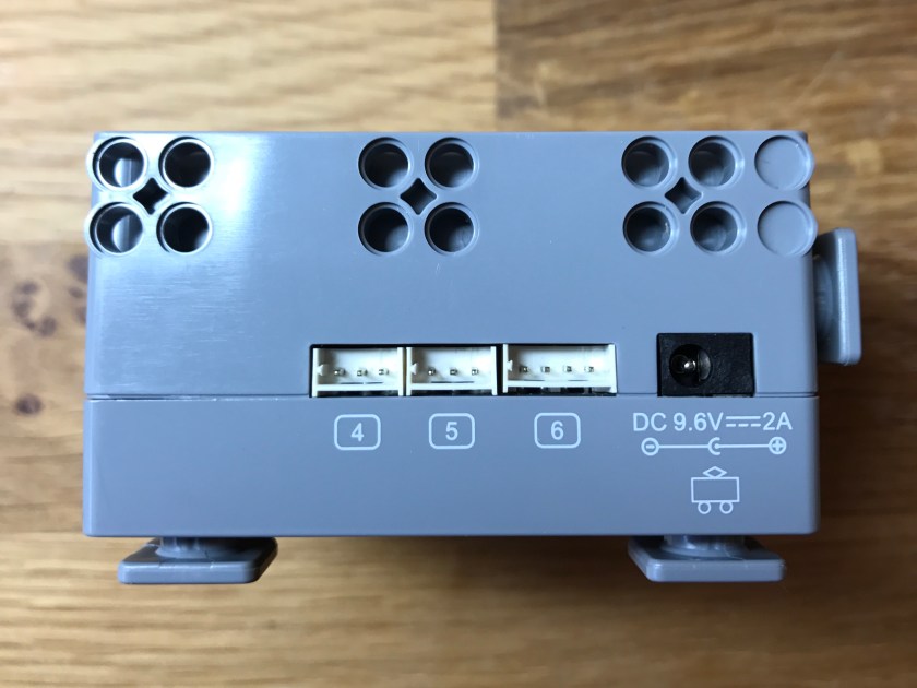
The first thing to notice, even before we open the case is that Jimu uses the same 3 pin connectors as Robotis XL-320 series (used in the MINI series) – specifically MOLEX Micro Latch 53254. The iPad application seems to be very insistent to make sure that the cables from servos are connected to the controller to the correct port number. I though that might mean that the ports might be independent – that would be an interesting achievement. But a quick check with the voltmeter confirmed that the 5 3-pin servo bus connectors are all working on the same bus and they are equivalent.
A further check indicated that the 3 pin connector is different from the Dynamixel one. First, the pins for DATA and GND are swapped:
- Pin 1 is DATA
- Pin 2 is VCC (servo power)
- Pin 3 is GND
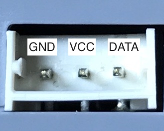
Second, it can be checked with an oscilloscope that the DATA pin uses 3.3V, something to keep in mind if you would be interested to accommodate a Robotis controller. We’ll see that in a future post.
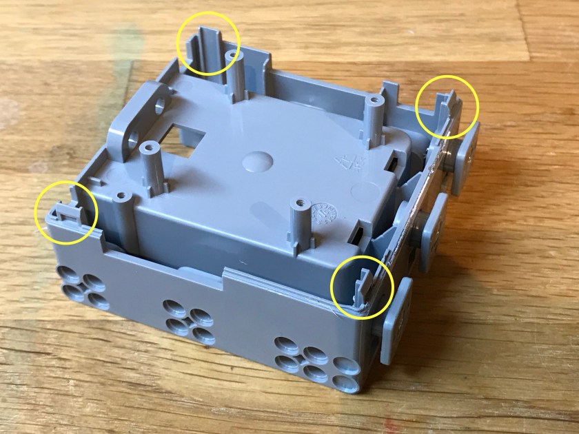
After taking out the 4 screws on the back of the controller I had to carefully take the cover off as there are 4 clips as you can see in the picture bellow:
Once open we can have a look at the board. First the back:

There is not a lot to see on this part except the Bluetooth module BM77SPP03MC2 that uses a IS1677SM chip and a i2c EEPROM. This is a 3.0 / 4.0 + EDR module, as mentioned also in the Jimu documentation, very suitable for today’s mobile devices.
It’s also nice to see that each 3-pin servo bus connector is nicely decoupled with a 100μF capacitor. Interestingly there is an empty connector for an additional UART and you can also see on top right the SWD connector for programming and debugging of the STM chip in the controller.
So let’s move to the front. I’ve marked the more interesting parts:

The board uses an STM32F070CB chip that has 128kbytes of FLASH and 16kbytes of RAM, as well as 37 GPIOs. It works at 48MHz which is less than the 72MHz that the processors in the Robotis boards are using (they use STM32F103 chips with CM-530 controller using an STM32F103RE that has 512Kbytes of FLASH). That might prove to provide some reduced performance when working with a larger number of devices (ex. in a humanoid with 16+ DOF and possibly some added sensors).
Bellow the processor there is a 32Mbit / 4Mbyte SPI FLASH chip (Winbond 25Q32JVSIQ). This is a puzzling design as I’m not really sure that the price of the STM32F070 plus this FLASH chip is cheaper than a STM32F with a more FLASH. Also, from what I have experienced with the iPad application until now the Jimu series relies on an external device (tablet or phone) to provide the program / instructions for the robot. There is no downloading of the program onto the controller and independent operation – like there is the case for Robotis robots (ex. Bioloid or MINI where you can build your program on a computer and then send it to the controller). This is why I find it odd to have such a large FLASH without any clear purpose. I’d would have rather liked a faster processor to be sincere.
To the right from the processor there is a small chip that I couldn’t 100% identify (it’s marked 25CZ) – but I suspect this is a 74LVC2G66 dual SPST switch for mixing the RX and TX on the communication bus. For those not familiar with the concept the serial bus uses only one DATA pin where TX and RX are multiplexed depending on the direction of communication. In other Jimu products they have opted for TS3A4741 (marking 8BLR – we’ll see those in the IR sensor and the LED device), but they seem to provide the same functionality. It’s quite interesting that the designers here used proper switches while all other Dynamixel compatible boards use 3-state buffers (like the 74LVC1G125 + 74LVC1G126 or 74LVC26241).
To the left of the processor there is the chip that is used to control the charging / discharging of the LiPo battery. It is a BQ24133. The presence of this is quite nice as this makes the usage of the product easier, not requiring to remove the battery in order to charge as it is the case for other robots. Of course the drawback is that you cannot charge another battery separately and then change them when needed. But frankly, I’ve noticed that the final design (at least for the AstroBot robot) would place the controller and the battery in such awkward positions that removing it would not really be practical. The battery charger uses a hi power MOSFT F9310 to switch the current to the battery.
There is a second F9310 used to switch on/off the power to the servo bus – a welcome functionality that is not available in all controllers from Robotis. So we should expect a command to the controller that turns the power on / off to the bus.
In the next posts I will start to hack through the communication protocol between the controller and the servos. It would be nice if UBTECH would publish these details at one point in time.
