In my previous posts I’ve just scratched the surface of the Jimu kits with a very high level overview of the content and then a fast breakdown of the controller hardware.
What I’m interested to understand is the communication protocol between the controller and the servos. Why? On one hand it would be interesting to understand more about the capabilities of the servos (as I mentioned in the previous posts there is practically no technical information about these parts) and also to break away from the tablet / phone app that is provided for the “programming” of the robots. That app is fine for children but we are grown ups, programmers if I may say, so it’s only natural to try to break this wall and see if we can use a more sophisticated programming approach.
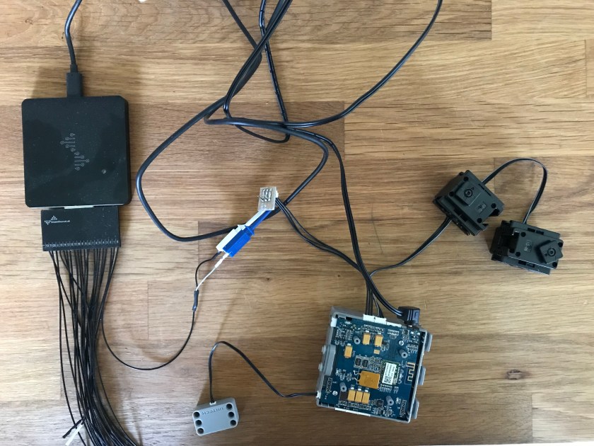
To hack this communication protocol I have connected two servos (no.1 and 5 – just picked them randomly, there is nothing special about them) to the controller, and on another connector (remember they are all connected together on one single communication bus) I have hooked a cable to a small connector that allows me to clip the cables from a logic analyser. The hookup looks like this:
For the time being the only way to send commands to the servos is through the tablet app, so I setup a custom robot with the 2 servos and in “Controls” I setup two sliders to control their positions:
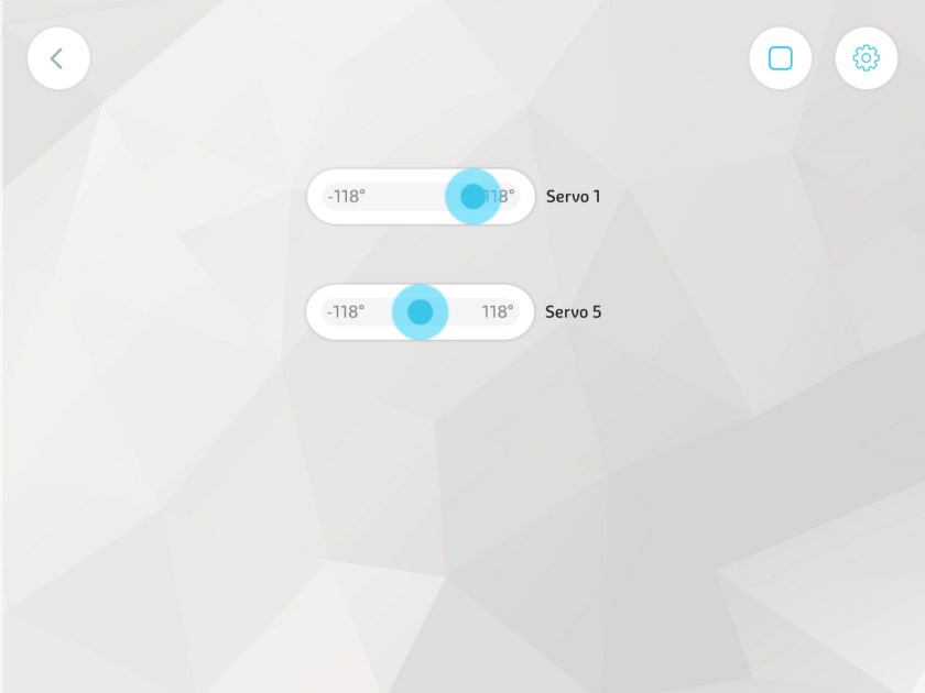
I can now move the sliders to different position and check on the analyser the content of the packages sent between the controller and the servos.
I’ve setup the analyser at 50MHz and the trigger on falling edge. In these controllers the bus is pulled up with 10k resistors and when starting to send data normally the standard serial protocols are used which means a 0 start bit. Therefore having a trigger on the filing edge is a good bet that we will get all the information from the start.
I picked the first servo and tapped randomly on the slider. Here is what I got:
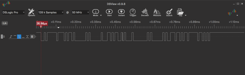
Nice, it seems to work, but as you might see (although it’s a little cramped in that picture) we are in for the first (bad) surprise: the communication seems to be at 115,200bps. This is disappointing considering that Robotis’ XL-320 servos (like it or not I will constantly compare the two systems because they are so close in design and there are obvious parallels between them) support up to 1Mbs transmission speed (they actually come by default with that speed). Why this matters? The higher the communication speed the more commands you can send to the servo in a period of time and this allows you to produce smoother movement and more natural look. As a drawback, higher speeds seem to create more headaches and are susceptible to data loss, especially if cables start to wear off. In a sense I understand the reasoning behind this decision for the guys at UBTECH: this is a toy aimed at children 8+ and you don’t want them to have to deal with such low level issues: if the communication doesn’t work and the robot is skipping moves there is a very good chance that the kit ends up on eBay quickly or is returned to the seller. But we don’t know if this is something that is inherently limited by the servos or just by the app we’re using. It might be possible that the servos have a way to adjust the communication speed, just like the Dynamixels. In the end it’s just based on the firmware that is in the servos, and frankly I don’t see what might be the stoppers for this to work. But for the time being we don’t know that and there doesn’t seem to be any control in the app to change the communication speed (controller or servos).
In the analyser we can now add a decoder to display the content of the package. We know it is a serial protocol and we can see the speed is 115,200. We expect to have 1 start bit (0) and one end bit (1) and 8 bits of data. With these settings the decoder shows this:
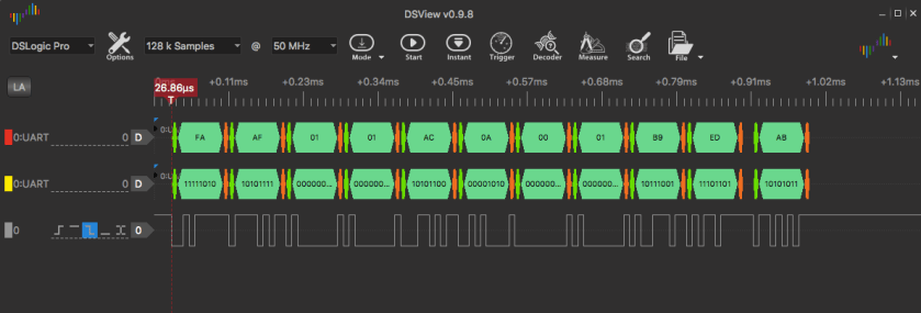
Ok, it looks familiar: we seem to have two bytes of a preamble: 0xFA, 0xAF, followed by two bytes of 0x01. One of them most likely is the ID of the servo, the other most likely is some sort of command (for Dynamixel the first would be the command and second the ID, but this remains to be seen when we play with servo ID 5). Then we have 4 bytes with data where the first one 0xAC seems to be to desired position. The one after that might be a register (like goal position in Dynamixel servos?) and then the last two 0x00 and 0x01 seem a little cryptic right no. Usually there is a checksum in the package – that could be either 0xB9 or the 0xED. The last byte (0xAB) seems to come a little later than the others – so it looks like the response from the servo.
The only way to know better is to send some more commands and see the packet content. I will not show you the analyser windows, just the content of the packages.
| Ser | Pos | Package content | Ans |
|---|---|---|---|
| 1 | -118° | 0xFA 0xAF 0x01 0x01 0x08 0x0A 0x00 0x01 0x15 0xED | 0xAB |
| 1 | 118° | 0xFA 0xAF 0x01 0x01 0xE1 0x0A 0x00 0x01 0xEE 0xED | 0xAB |
| 5 | -118° | 0xFA 0xAF 0x05 0x01 0x02 0x0A 0x00 0x01 0x13 0xED | 0xAF |
| 5 | 118° | 0xFA 0xAF 0x05 0x01 0xE0 0x0A 0x00 0x01 0xF1 0xED | 0xAF |
Ok, we seem to find some patterns:
- the communication package seem to start with 0xFA 0xAF – similar to the approach in Dynamixel communication, although the markers are different
- the next byte seems to be the ID of the servo that we are communicating with; you see in the first 2 rows the code is 1 and in the other two is 5 – precisely the code of the servo that we are communicating with
- we then have a code 0x01 that is the same in all packages; this seems to be the instruction byte; in the case of Dynamixel the meaning of this byte was “write register”, “read register”, “ping”, etc. We don’t know for sure what exactly is the meaning of the 0x01 in this case – but it seems to be the one that provides a “go to” instruction.
- the next byte seems to be the actual position where we send the servo to
- the next byte might be the address where the value (position) should be saved in the servo (that’s the Dynanixel approach) – but in our case it might be something else and we’ll need to investigate more
- the next two bytes are 0x00 and 0x01 in all commands so we cannot say for sure what is this about
- the next byte seems to be a checksum as we expected; it is specifically the simple (mod) sum of the bytes after the preamble 0xFA 0xAF
- the last one also seems to be 0xED in all cases and looks like a terminator for the command (maybe from “END”)
- the answers seem to be different between the two servos but consistent for each servo alone
To try to analyse more carefully the content of the package we will use the ability to create actions where we can define for several servos the desired positions and durations and trigger them in one go. I’ve created 3 actions: one that puts both servos at 0° in 200ms, one that sends them at -45° in 400ms and one that sends them at 45° in 800ms. When triggering each of these actions we can see the train of communication and learn how the controller does things. For instance when initiating the first action (go to 0°) the train looks like this:
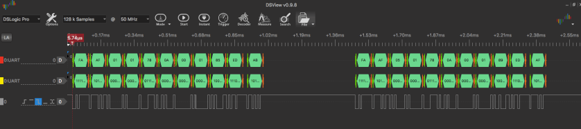
At this moment we have a second disappointment: the commands for the two servos seem to be sent in separate packages instead of using a “bulk command” instruction. This means we will have even worse performance when driving a larger number of servos. You can also see in the picture above that there is an added 0.478ms delay between the end of one package and the start of the other, as if the controller waits a little before starting with the next package. In total it seems to take 1.5ms to send one command to one servo. For a humanoid robot with 16 DOF (like the one from Jimu) it would take 16 x 1.5 = 24ms to send commands to all servos at a given time which means we would have a maximum theoretical sync frequency of 41.67Hz. That might be enough on paper but it will deteriorate if the number of servos goes up (a more natural number for a humanoid is closer to 20 if not 24) and additional sensors are added in the picture.
Looking now at the trains for the actions we have the following results:
| Pos | Dur | Package content | Ans |
|---|---|---|---|
| 0° | 200 | 0xFA 0xAF 0x01 0x01 0x78 0x0A 0x00 0x01 0x85 0xED | 0xAB |
| 0° | 200 | 0xFA 0xAF 0x05 0x01 0x78 0x0A 0x00 0x01 0x89 0xED | 0xAF |
| -45° | 400 | 0xFA 0xAF 0x01 0x01 0x48 0x14 0x00 0x01 0x62 0xED | 0xAB |
| -45° | 400 | 0xFA 0xAF 0x05 0x01 0x48 0x14 0x00 0x01 0x66 0xED | 0xAF |
| 45° | 800 | 0xFA 0xAF 0x01 0x01 0xA5 0x28 0x00 0x01 0xD0 0xED | 0xAB |
| 45° | 800 | 0xFA 0xAF 0x05 0x01 0xA5 0x28 0x00 0x01 0xD4 0xED | 0xAF |
We can see a little bit more clear now the meaning of some of the parameters:
- the byte 5 indicates the target position and seems to be the exact value of the angle plus 120 (degree); so, for a 0° the value is 0 + 120 = 120 = 0x78. For -45° the parameter passed is -45 + 120 = 75 = 0x48, and so on. The small differences we had between the rows in the first table seem to have been due to the imperfect ability to accurately control the position of a servo from those sliders
- the byte 6 is not a register but seems to indicate the duration of the movement: for 200ms the value is 0x0A, for 400ms is 0x14 (which is exactly double) and for 800ms is 0x28 which is again double. The parameter seems to be the duration in 20ms increments (for example the duration / 20). This again seems to be consistent with the fact that the maximum duration for an action that can be setup in the app is 5000ms which would be roughly the 256 (the maximum you can store in 8 bit) x 20ms.
For the time being here is a summary of the finds:
- the communication is at 115,200bps
- packages are send separately by servo; it doesn’t seem to be a “bulk send” instruction
- the package has the following structure:
-
- byte 1 and 2 = preamble = 0xFA 0xAF
- byte 3 = Servo ID
- byte 4 = Command; for “go to command” we have = 0x01; we will try to find some other commands shortly
- byte 5 – 8 = Command parameters; for command = 0x01 (go to) they are:
-
- byte 5 = position = 120 + desired position in degrees
- byte 6 = duration = duration in ms / 20
- byte 7 = 0x00 (? we don’t know what this is yet)
- byte 8 = 0x01 (? we don’t know what this is yet)
- byte 9 = checksum = sum(byte 3 through 8) mod 256
- byte 10 = closure = 0xED (from “END”?)
- the servo returns one byte that seems to contain something specific to the ID of the servo (for ID 1 it answers with 0xAB, for 5 it answers with 0xAF; the content could be a status information where each bit has a meaning, similar to the status packet in the Dynamixel protocol
It was quite interesting and in the next days I will try to keep on digging in the communication. In a future post I will present some ways of hooking the servos to a normal Robotis serial converter and some code written on my laptop instead of using the Jimu controller and the tablet app.
Remember: the DATA and GND pins are swapped compared to the Dynamixel bus and the DATA is 3.3V logic.
